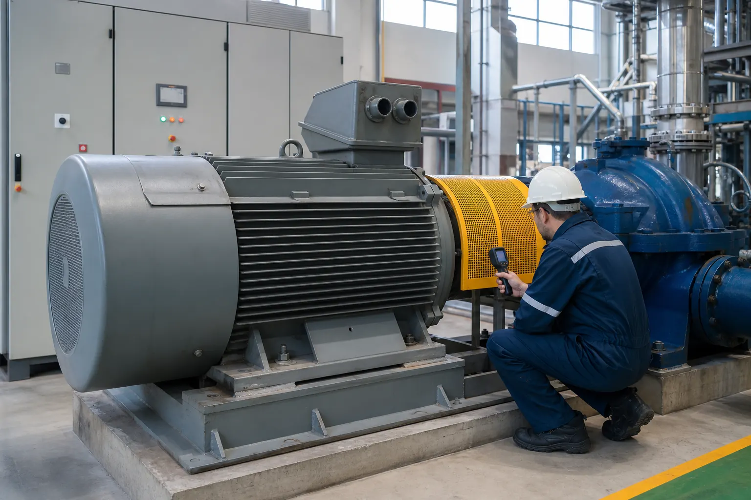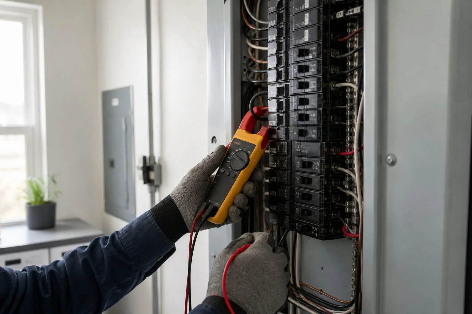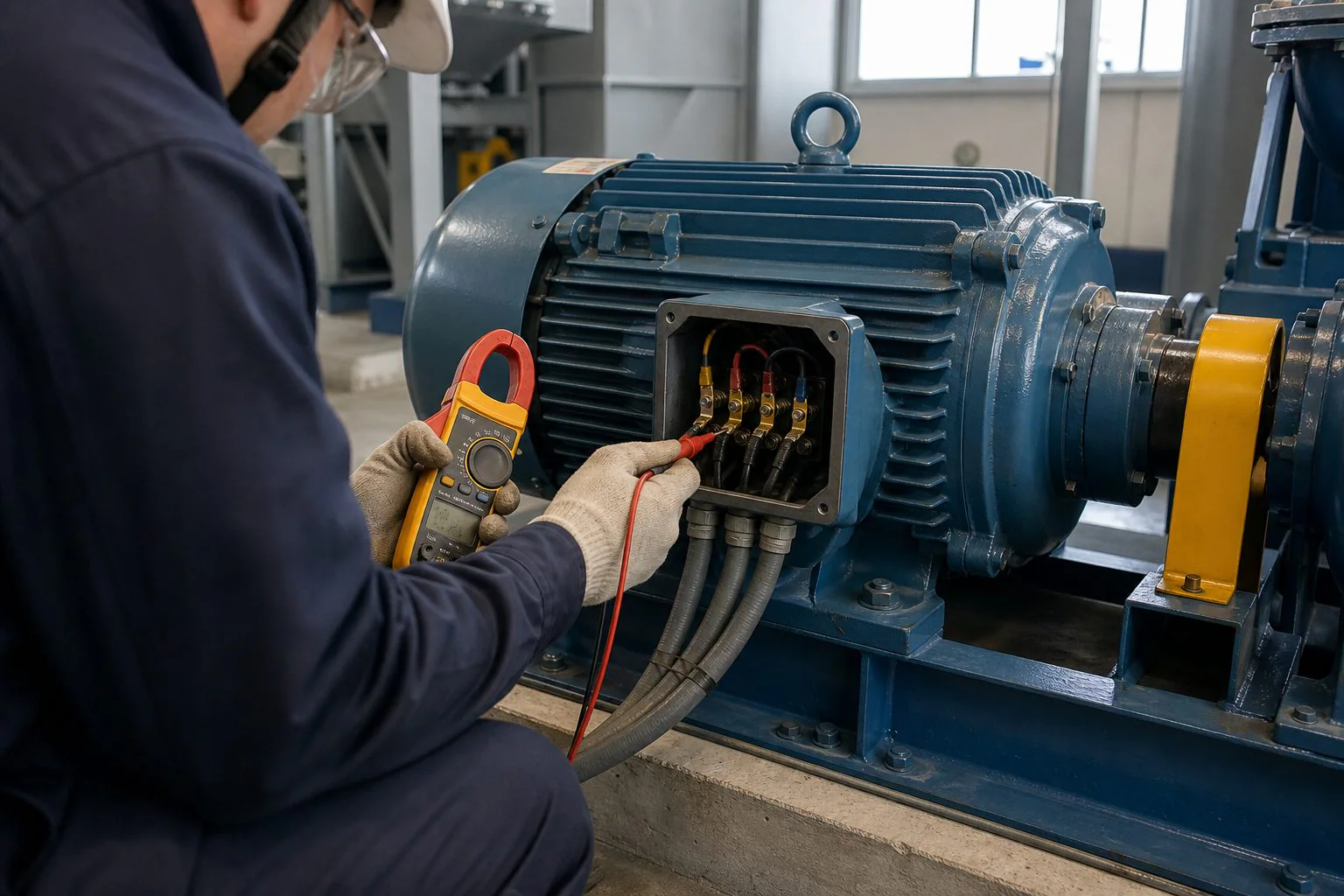
A motor amps chart provides a quick reference for estimating the full-load current of an electric motor from its horsepower, voltage, and phase. It can help with early equipment planning, load estimates, and comparisons, but it does not replace the motor nameplate or the electrical code used for the installation.
A 5 HP three-phase motor, for example, may have a reference full-load current of about 15.2 A at 230 V or 7.6 A at 460 V. A 5 HP single-phase motor can have a much higher reference current—about 28 A at 230 V. Voltage and phase clearly matter.
There is another complication: nameplate full-load amps, code-table full-load current, calculated current, and measured running current are not necessarily identical. Each value serves a different purpose. This guide provides practical single-phase and three-phase tables while explaining how to use them correctly.
Quick Motor Amps Chart
The following values are general full-load-current references for common AC motors. Confirm the applicable standard, code edition, motor type, and nameplate before using them for electrical design.
Single-phase AC motor current
| Motor HP | 115 V | 230 V |
|---|---|---|
| 1/6 HP | 4.4 A | 2.2 A |
| 1/4 HP | 5.8 A | 2.9 A |
| 1/3 HP | 7.2 A | 3.6 A |
| 1/2 HP | 9.8 A | 4.9 A |
| 3/4 HP | 13.8 A | 6.9 A |
| 1 HP | 16.0 A | 8.0 A |
| 1.5 HP | 20.0 A | 10.0 A |
| 2 HP | 24.0 A | 12.0 A |
| 3 HP | 34.0 A | 17.0 A |
| 5 HP | 56.0 A | 28.0 A |
| 7.5 HP | 80.0 A | 40.0 A |
| 10 HP | 100.0 A | 50.0 A |
Three-phase AC motor current
| Motor HP | 200 V | 230 V | 460 V | 575 V |
|---|---|---|---|---|
| 1/2 HP | 2.5 A | 2.2 A | 1.1 A | 0.9 A |
| 3/4 HP | 3.7 A | 3.2 A | 1.6 A | 1.3 A |
| 1 HP | 4.8 A | 4.2 A | 2.1 A | 1.7 A |
| 1.5 HP | 6.9 A | 6.0 A | 3.0 A | 2.4 A |
| 2 HP | 7.8 A | 6.8 A | 3.4 A | 2.7 A |
| 3 HP | 11.0 A | 9.6 A | 4.8 A | 3.9 A |
| 5 HP | 17.5 A | 15.2 A | 7.6 A | 6.1 A |
| 7.5 HP | 25.3 A | 22.0 A | 11.0 A | 9.0 A |
| 10 HP | 32.2 A | 28.0 A | 14.0 A | 11.0 A |
| 15 HP | 48.3 A | 42.0 A | 21.0 A | 17.0 A |
| 20 HP | 62.1 A | 54.0 A | 27.0 A | 22.0 A |
| 25 HP | 78.2 A | 68.0 A | 34.0 A | 27.0 A |
| 30 HP | 92.0 A | 80.0 A | 40.0 A | 32.0 A |
| 40 HP | 120.0 A | 104.0 A | 52.0 A | 41.0 A |
| 50 HP | 150.0 A | 130.0 A | 65.0 A | 52.0 A |
| 60 HP | 177.0 A | 154.0 A | 77.0 A | 62.0 A |
| 75 HP | 221.0 A | 192.0 A | 96.0 A | 77.0 A |
| 100 HP | 285.0 A | 248.0 A | 124.0 A | 99.0 A |
These are reference values for motors with common speed and torque characteristics, not universal nameplate ratings. Special motors, multispeed designs, high-torque applications, wound-rotor machines, synchronous motors, and VFD systems may require different data.
What Full-Load Amps Mean
Full-load amps, abbreviated FLA, describe the current a specific motor is rated to draw when producing its rated output under the nameplate conditions. Those conditions include voltage, frequency, phase, power factor, efficiency, speed, and duty.
For the specific motor, the nameplate is the primary source of rated operating information. ABB’s guide to reading a NEMA motor nameplate explains that power factor must be considered because the simple relationship between watts, volts, and amps does not fully describe an AC motor.
A motor does not necessarily draw its full-load amperage whenever it is switched on. Current changes with mechanical load. A lightly loaded motor may draw less real power than it does at rated output, although its no-load current can still be substantial because magnetizing current is required to establish the rotating magnetic field.
The measured running current should normally be checked on every phase of a three-phase motor. One phase reading alone can hide current imbalance or a supply problem.
Nameplate FLA, Code-Table FLC, and Measured Current
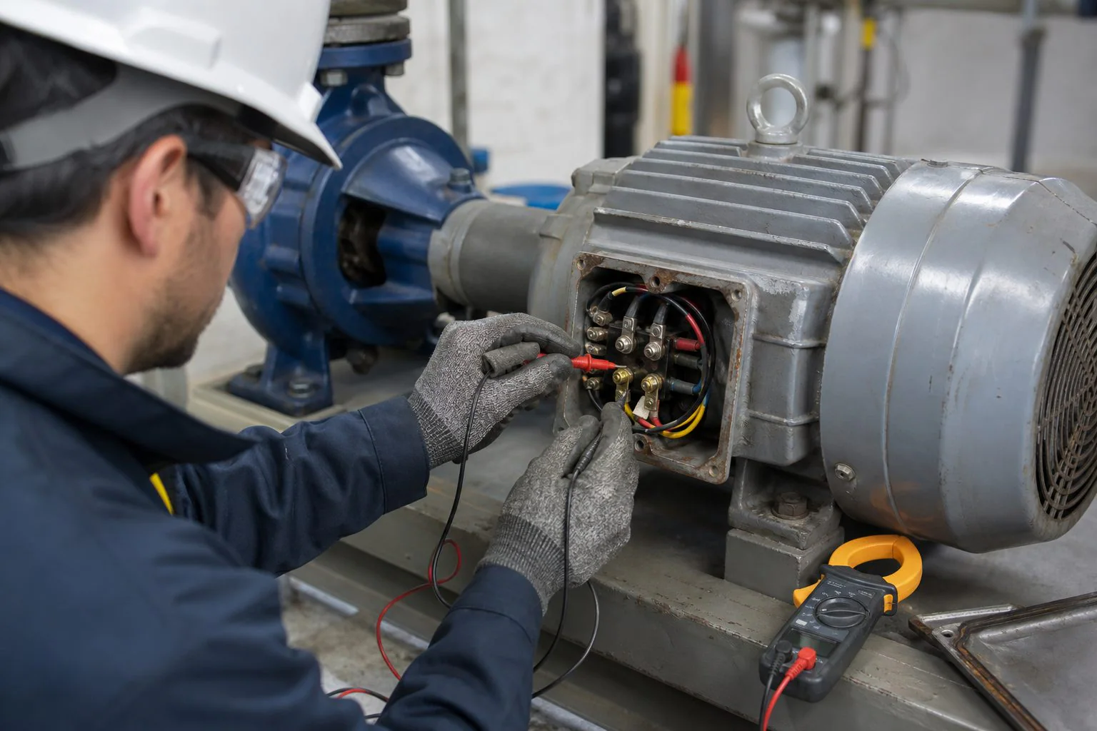
Three values often appear during motor planning and troubleshooting.
Nameplate full-load amps
Nameplate FLA applies to the actual motor. Manufacturers determine it from the motor’s design and rated operating conditions. It is commonly used for settings and decisions that specifically require nameplate current.
Code-table full-load current
A code-table value is often called FLC rather than FLA. It is a standardized current assigned by horsepower, voltage, phase, and motor type for particular installation calculations.
In NEC-based work, Table 430.248 addresses many single-phase AC motors, while Table 430.250 covers many three-phase AC motors. The official NFPA material describes its three-phase values as typical for motors operating at usual speeds with normal torque characteristics. The NFPA 70 development page should be consulted alongside the locally adopted edition.
A table value can be higher than the motor’s nameplate current. That difference is not automatically an error.
Measured running current
Measured current reflects the motor’s actual operating condition at that moment. It changes with shaft load, supply voltage, phase balance, power quality, temperature, and the way the motor is controlled.
Because these three values answer different questions, the highest or lowest number is not automatically the “correct” one for every task.
How to Calculate Motor Current
A formula can estimate current when a chart is unavailable, particularly for IEC motors rated in kilowatts. However, efficiency and power factor are required when the stated kW or HP represents mechanical output.
One horsepower equals approximately 746 watts:
Output watts = HP × 746
Single-phase motor formula
For single-phase AC:
I = Output watts ÷ (V × PF × η)
Where:
- I is current in amps
- V is voltage
- PF is power factor
- η is motor efficiency expressed as a decimal
Consider a 5 HP single-phase motor at 230 V, with 0.85 power factor and 85% efficiency:
Output power = 5 × 746 = 3,730 W
I = 3,730 ÷ (230 × 0.85 × 0.85)
I ≈ 22.45 A
This calculated result differs from a standardized chart value because the assumed efficiency and power factor may not represent the design basis of that table or the specific motor.
Three-phase motor formula
For a balanced three-phase motor using line-to-line voltage:
I = Output watts ÷ (√3 × V × PF × η)
The value of √3 is approximately 1.732.
For a 10 HP motor at 460 V, assuming a power factor of 0.86 and efficiency of 90%:
Output power = 10 × 746 = 7,460 W
I = 7,460 ÷ (1.732 × 460 × 0.86 × 0.90)
I ≈ 12.10 A
The reference table shows 14 A for a common 10 HP, 460 V three-phase motor. This illustrates why a calculated estimate should not be substituted blindly for a required code-table or nameplate value.
Motor kW-to-Amps Reference
Motor ratings outside North America often use kilowatts rather than horsepower. The following three-phase motor kW-to-amps chart provides calculated estimates at 400 V and 415 V.
Assumptions: 90% efficiency and 0.85 power factor for every row. Actual values vary by motor size, design, load, and efficiency class.
| Motor output | Current at 400 V | Current at 415 V |
|---|---|---|
| 0.75 kW | 1.42 A | 1.36 A |
| 1.1 kW | 2.08 A | 2.00 A |
| 1.5 kW | 2.83 A | 2.73 A |
| 2.2 kW | 4.15 A | 4.00 A |
| 3 kW | 5.66 A | 5.46 A |
| 4 kW | 7.55 A | 7.28 A |
| 5.5 kW | 10.38 A | 10.01 A |
| 7.5 kW | 14.15 A | 13.64 A |
| 11 kW | 20.75 A | 20.00 A |
| 15 kW | 28.30 A | 27.28 A |
| 18.5 kW | 34.90 A | 33.65 A |
| 22 kW | 41.51 A | 40.01 A |
| 30 kW | 56.60 A | 54.55 A |
| 37 kW | 69.80 A | 67.28 A |
| 45 kW | 84.90 A | 81.83 A |
| 55 kW | 103.77 A | 100.02 A |
Treat these figures as calculation examples, not nameplate predictions. A larger premium-efficiency motor may have different full-load efficiency and power factor from a small motor. Applying identical assumptions across every rating creates a convenient comparison, but not a manufacturer-specific result.
Why Single-Phase Motors Draw More Current
A single-phase and a three-phase motor can produce the same mechanical output but draw different line currents.
Three-phase power distributes energy across three phase conductors and produces a naturally rotating magnetic field. For balanced three-phase calculations, the power equation includes the √3 factor. Three-phase motors also commonly achieve favorable efficiency and power delivery in larger industrial applications.
Compare the reference values for a 5 HP motor:
- 230 V single phase: approximately 28 A
- 230 V three phase: approximately 15.2 A
- 460 V three phase: approximately 7.6 A
Moving from single-phase to three-phase supply reduces the line current for comparable output. Increasing voltage also reduces current. That does not mean a motor can be connected to any convenient voltage or phase arrangement. Its winding connections and nameplate ratings must match the supply and starting method.
Why Motor Current Changes With Voltage
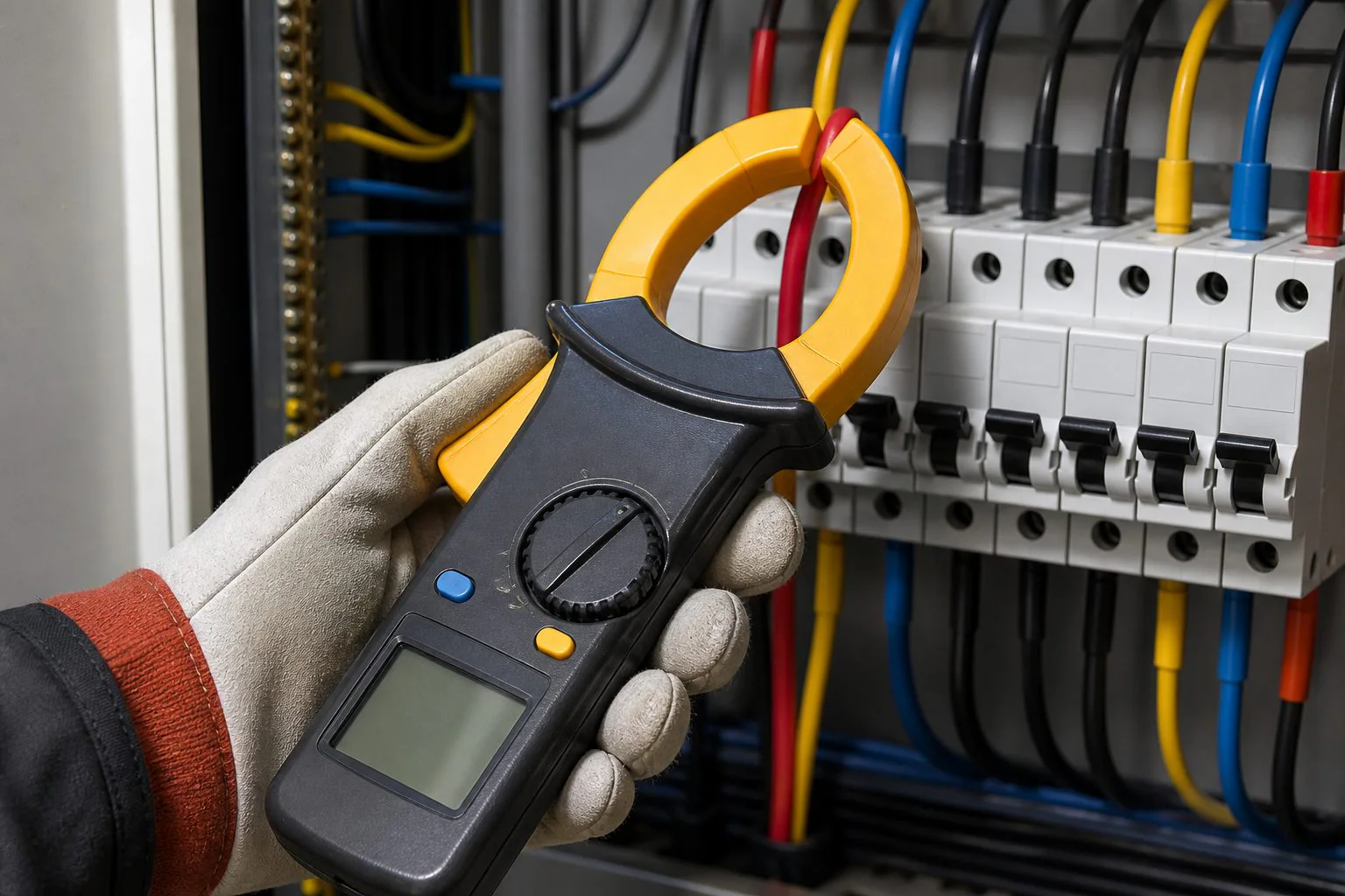
For a given power level, current generally falls as voltage rises. The three-phase chart shows this clearly: many reference currents at 460 V are approximately half their corresponding values at 230 V.
However, a motor connected below its rated voltage does not simply operate as a constant-power mathematical load under every condition. Low voltage can reduce available torque and cause the motor to draw excessive current while attempting to carry its mechanical load. That can increase heating and shorten insulation life.
Voltage imbalance is particularly harmful to a three-phase motor because a relatively small voltage imbalance can create a larger current imbalance. If one phase current is noticeably different, check all phase-to-phase voltages, connections, load conditions, and motor condition.
A dual-voltage motor must also be connected correctly for the supply. The winding configuration shown on the nameplate or connection diagram is not optional.
Running Current Is Not Starting Current
The values in a full-load motor current chart are not startup amperage.
When an induction motor starts directly across the line, the rotor is initially stationary and the motor can draw several times its full-load current. The exact locked-rotor current depends on motor design, horsepower, voltage, NEMA code letter, and starting method.
This high current usually lasts only while the motor accelerates. A load with high inertia or high starting torque can extend the acceleration period and increase heating.
Starting methods include:
- direct-on-line or across-the-line starting
- star-delta or wye-delta starting
- autotransformer starting
- reduced-voltage starting
- soft starters
- variable-frequency drives
A soft starter limits voltage during acceleration, while a VFD controls motor frequency and voltage. Neither should be selected solely from a basic HP-to-amps chart. The driven load, starting torque, acceleration time, starts per hour, bypass arrangement, enclosure, ambient temperature, and manufacturer requirements all matter.
Reading the Motor Nameplate
Before using a motor current calculator or table, record the nameplate information.
Useful fields include:
- manufacturer and model
- horsepower or kilowatt rating
- voltage
- full-load amps
- phase
- frequency
- speed in RPM
- efficiency
- power factor
- service factor
- duty rating
- insulation class
- temperature rise
- enclosure type
- frame size
- NEMA design letter
- locked-rotor code letter
A dual-voltage motor usually shows two amperage values. The lower-voltage connection draws more current. For example, a plate might show 230/460 V and 14/7 A. The motor current approximately halves when the rated voltage doubles.
The nameplate diagram should be followed when reconnecting windings. Incorrect connections can cause improper rotation, excessive current, low torque, or winding damage.
What Causes High Motor Amps?
Current above the expected value is a symptom, not a complete diagnosis.
Possible causes include excessive mechanical load, low voltage, voltage imbalance, a missing phase, incorrect winding connections, bearing problems, misalignment, binding equipment, frequent starts, inadequate acceleration, poor ventilation, high ambient temperature, internal winding faults, or an incorrect VFD setup.
For a pump or fan, a process change can overload the motor even when the electrical system is healthy. A clogged or restricted mechanical system can also alter operating conditions.
Useful troubleshooting steps include comparing all three phase currents, measuring phase-to-phase voltages, checking the driven load, reviewing the nameplate, and comparing the current with the motor’s normal historical readings.
Do not continue resetting a tripped overload without finding the cause. Repeated tripping can indicate a mechanical, electrical, control, or motor problem requiring qualified investigation.
Using FLA for Wire, Breaker, and Overload Sizing
A motor’s conductor, short-circuit protection, ground-fault protection, and overload protection do not necessarily use the same current value or percentage.
That distinction is easy to miss:
- Branch-circuit conductors protect the wiring from overheating.
- A fuse or circuit breaker addresses short circuits and ground faults under the applicable rules.
- An overload relay protects the motor from sustained overcurrent and overheating.
- A starter or contactor must be able to switch the motor load.
- A disconnect must meet the relevant duty and rating requirements.
The breaker may therefore be rated higher than someone expects after looking only at the motor FLA. This does not mean overload protection has been omitted; the devices address different hazards.
Likewise, multiplying a chart value by one percentage cannot produce every required component rating. Code edition, motor type, starting method, conductor conditions, protection type, and exceptions all affect the result.
Siemens notes that starter selection depends on the motor’s nameplate FLA and the application rather than horsepower alone. Its documentation also warns that rated nameplate current may differ considerably from general listed values because motor designs vary.
Use the locally adopted electrical code and manufacturer instructions, and have the final motor circuit designed or reviewed by a qualified professional.
Common Mistakes With Motor Current Tables
The first mistake is treating a reference chart as the exact current of every motor with the same horsepower. Efficiency, power factor, speed, service factor, and design can change the nameplate value.
A second mistake is using mechanical output power as though it were electrical input power. Dividing motor kW by voltage without including efficiency and power factor understates current.
Other frequent errors include using the single-phase formula for a three-phase motor, forgetting √3, using line-to-neutral voltage in a line-to-line formula, confusing nominal system voltage with motor-rated voltage, and treating full-load current as locked-rotor current.
It is also unsafe to choose a cable, breaker, fuse, overload setting, or VFD from one table without checking the rules and equipment documentation that apply to that component.
Frequently Asked Questions
What is a motor amps chart?
It is a reference table showing estimated or standardized motor current by horsepower, voltage, and phase. Depending on its source, the table may present code full-load current rather than the exact nameplate amps of a specific motor. Always check the chart’s assumptions and intended use.
How many amps does a 1 HP motor draw?
A common reference value for a 1 HP motor is about 16 A at 115 V single phase, 8 A at 230 V single phase, 4.2 A at 230 V three phase, or 2.1 A at 460 V three phase. Actual nameplate current may differ.
How many amps does a 5 HP motor draw?
Typical reference values are approximately 28 A at 230 V single phase, 15.2 A at 230 V three phase, and 7.6 A at 460 V three phase. Use the motor nameplate for its rated current and the required code table for applicable installation calculations.
How many amps does a 10 HP motor draw?
A common reference current is about 50 A at 230 V single phase, 28 A at 230 V three phase, or 14 A at 460 V three phase. Motor design, speed, efficiency, power factor, and service factor can change the nameplate rating.
What is the difference between FLA and FLC?
FLA commonly refers to the full-load amps marked for a specific motor. FLC often refers to a standardized full-load current from an electrical code table. The numbers may differ, and the applicable rule determines which one should be used for a particular calculation.
Why is measured motor current lower than the chart?
The motor may be operating below its rated mechanical load, or its design may be more efficient than the assumptions behind the chart. Supply voltage and measurement conditions also matter. Compare measured current with the nameplate rating and verify that all phases are reasonably balanced.
How much current does a motor draw during startup?
An induction motor started directly across the line can draw several times its full-load current. The exact value and duration depend on motor design, locked-rotor code, supply voltage, driven-load inertia, starting torque, and starting method. Use manufacturer data for coordination studies.
Can I size a breaker from motor FLA?
Not from FLA alone. Motor breaker selection depends on the applicable electrical code, motor type, protective-device type, starting characteristics, conductor sizing, and other installation details. Motor overload protection and branch-circuit short-circuit protection are separate functions and may use different calculations.
Use the Chart as a Reference, Not a Nameplate Replacement
A motor amps chart is valuable for comparing horsepower, voltage, and phase before detailed equipment information is available. It quickly shows why three-phase motors usually draw less line current than comparable single-phase units and why current falls as rated voltage rises.
For the final design, identify whether the task requires nameplate FLA, code-table FLC, calculated input current, or measured running current. Then use the appropriate code edition, manufacturer documentation, and qualified electrical judgment for conductors, starters, overloads, fuses, breakers, VFDs, and other protection.