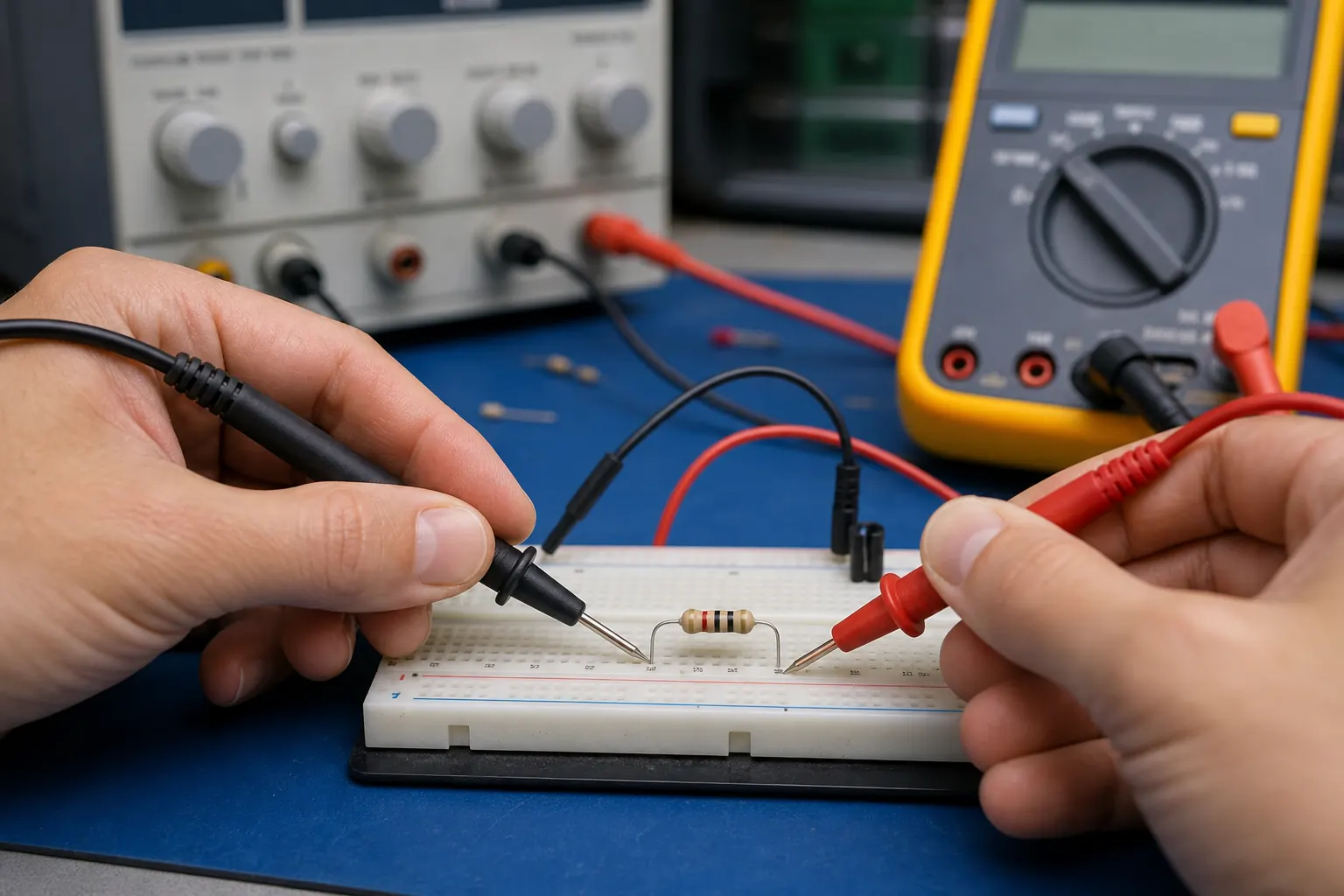
The voltage across the resistor is the difference in electric potential between its two terminals. If the current and resistance are known, calculate it with Ohm’s Law:
V_R = I × R
The required method changes with the circuit. Voltage divides among resistors connected in series, while resistors connected directly between the same two parallel nodes have equal voltage. You can also subtract the voltage at one terminal from the voltage at the other.
This distinction matters because voltage does not flow through a resistor. Current flows through it, while voltage describes the energy difference per unit charge between two points. Before calculating, label both resistor terminals, choose a polarity, and identify whether the resistor is alone, in series, in parallel, or part of a loaded divider.
Quick Answer
To find the voltage across a resistor, multiply the current through it by its resistance:
V_R = IR
For a series network with a known supply voltage, use:
V_R_x = V_S(R_x) ÷ (R_T)
For parallel resistors connected to the same two nodes:
V_R1 = V_R2 = V_branch
The answer represents potential difference between the resistor’s terminals, not voltage at one isolated point.
Begin With the Resistor’s Two Terminals
Voltage requires two points. Suppose a resistor is connected between terminal A and terminal B. Define its voltage as:
V_AB = V_A-V_B
Here, (V_A) and (V_B) are node voltages measured relative to the same reference, often called ground.
If terminal A is at 11.8 V and terminal B is at 4.6 V:
V_AB = 11.8-4.6
V_AB = 7.2 V
This says terminal A is 7.2 V higher than terminal B. Reverse the reference and the sign changes:
V_BA = 4.6-11.8 = -7.2 V
Both calculations describe the same physical potential difference. The negative result simply indicates that the actual polarity is opposite to the reference chosen for (V_{BA}).
This terminal-based view prevents a common mistake. A circuit node may be at 11.8 V relative to ground, but that does not mean every component connected to that node has 11.8 V across it. The voltage across each component depends on the potential at both of its terminals.
Calculate Voltage Across the Resistor With Ohm’s Law
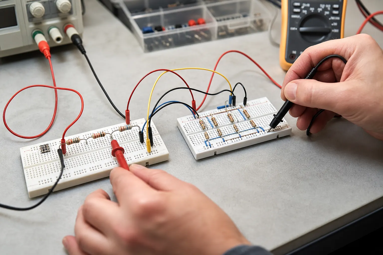
For an ohmic resistor operating under conditions where its resistance is reasonably constant, use:
V_R = I × R
Where:
- (V_R) is resistor voltage in volts
- (I) is current through the resistor in amperes
- (R) is resistance in ohms
A current of 7.5 mA passes through a 680 Ω resistor. Convert milliamperes to amperes first:
7.5 mA = 0.0075 A
Substitute the values:
V_R = 0.0075 × 680
V_R = 5.1 V
The unit check supports the answer:
A × Ω = V
Mixing amperes and kilo-ohms can also produce volts directly because:
1 mA × 1 kΩ = 1 V
However, this shortcut is safe only when the prefixes match correctly. For example, multiplying milliamperes by ordinary ohms does not produce volts without an additional factor of 1,000.
More related equations are available in the site’s electrical current formulas.
When Does One Resistor Have the Full Source Voltage?
A single resistor connected directly between the two terminals of an ideal voltage source has the full source voltage across it.
For a 12 V ideal source connected only to a 4 Ω resistor:
V_R = 12 V
The resulting current is:
I = (V_R) ÷ (R)
I = (12) ÷ (4) = 3 A
This does not mean a resistor always receives the full supply voltage. The statement changes if the circuit contains other series components, source internal resistance, meaningful conductor resistance, or a current-limited source.
For example, if a real source has internal resistance, some voltage may appear across that internal resistance while current flows. The external resistor then receives the source’s loaded terminal voltage, which can be lower than its no-load value.
How Voltage Divides Across Series Resistors
Resistors are in series when they form one current path with no branching between them. The same current passes through every series resistor, but the voltage drop across each resistor depends on its resistance.
First calculate total resistance:
R_T = R_1+R_2+ × s+R_n
Then find circuit current:
I = (V_S) ÷ (R_T)
The voltage across an individual resistor is:
V_R_x = I × R_x
You can combine these equations to obtain the voltage-divider rule:
V_R_x = V_S × (R_x) ÷ (R_T)
Consider an 18 V source connected to two series resistors:
R_1 = 1.2 kΩ
R_2 = 3.3 kΩ
Total resistance is:
R_T = 1.2+3.3 = 4.5 kΩ
Convert the total to 4,500 Ω and calculate current:
I = (18) ÷ (4500) = 0.004 A
I = 4 mA
The first resistor’s voltage drop is:
V_R1 = 0.004 × 1200 = 4.8 V
The second resistor’s voltage drop is:
V_R2 = 0.004 × 3300 = 13.2 V
The larger resistor receives the larger share of the supply because the current is identical through both resistors.
Kirchhoff’s Voltage Law provides a useful check:
V_S = V_R1+V_R2
18 = 4.8+13.2
If the voltage drops do not add to the applied source voltage in this ideal single-loop example, recheck the resistance values, unit conversions, signs, or arithmetic.
Why Parallel Resistors Have the Same Voltage
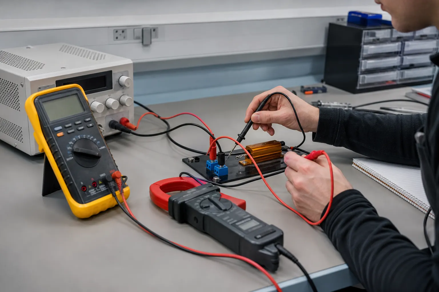
Components connected in parallel share the same two circuit nodes. Because voltage is the potential difference between two nodes, every component connected between that same pair has the same voltage.
Suppose a 2.2 kΩ resistor and a 4.7 kΩ resistor are connected directly across a 9 V source:
V_R1 = V_R2 = 9 V
Their voltages match, but their currents do not:
I_1 = (9) ÷ (2200)≈4.09 mA
I_2 = (9) ÷ (4700)≈1.91 mA
The lower-resistance branch carries more current.
The rule applies to branches sharing the same two nodes. It does not mean every resistor anywhere in a circuit has the source voltage. In a mixed network, an entire parallel group may be in series with another component. The parallel branches share the voltage across their group, which may be only part of the total supply.
Finding Resistor Voltage in a Mixed Network
For a series-parallel network, simplify the circuit in stages. Combine the parallel section first, then use the resulting equivalent resistance to calculate total current.
Consider a 12 V source with a 1 kΩ resistor in series with two 2 kΩ resistors connected in parallel.
The equivalent resistance of the parallel pair is:
R_P = (R_2R_3) ÷ (R_2+R_3)
R_P = (2000 × 2000) ÷ (2000+2000) = 1000 Ω
Total resistance is:
R_T = 1000+1000 = 2000 Ω
Source current is:
I_T = (12) ÷ (2000) = 0.006 A
I_T = 6 mA
The series 1 kΩ resistor drops:
V_R1 = 0.006 × 1000 = 6 V
That leaves 6 V across the parallel section. Since both parallel resistors connect to the same two nodes:
V_R2 = V_R3 = 6 V
Current divides between those branches, but the branch voltage remains equal.
The Loaded Voltage-Divider Problem
A two-resistor voltage divider produces an output that is a fraction of its input:
V_out = V_in × (R_2) ÷ (R_1+R_2)
This standard formula assumes the output is unloaded, or that the connected load has a resistance high enough to have negligible effect.
Suppose:
V_in = 15 V
R_1 = 10 kΩ
R_2 = 20 kΩ
The unloaded output across (R_2) is:
V_out = 15 × (20) ÷ (10+20)
V_out = 10 V
Now connect a 20 kΩ load (R_L) across (R_2). The load and lower resistor are in parallel:
R_lower = R_2\parallel R_L
R_lower = (R_2R_L) ÷ (R_2+R_L)
R_lower = (20 × 20) ÷ (20+20) = 10 kΩ
The loaded divider is now effectively 10 kΩ over 10 kΩ:
V_out = 15 × (10) ÷ (10+10)
V_out = 7.5 V
The output fell from 10 V to 7.5 V because the load changed the divider’s lower resistance. A resistor divider does not act like an ideal fixed-voltage supply. Its output depends on the connected load.
This behavior matters when a divider feeds a sensor input, analog-to-digital converter, transistor stage, or other circuit with finite input resistance.
Polarity, Voltage Drop, and Negative Answers
The phrase “voltage drop” usually assumes a direction. Under the passive sign convention, current enters the terminal marked positive and leaves the terminal marked negative. Moving in the current direction across a resistor is then treated as a potential drop.
If you label the polarity in the opposite direction, the calculated voltage will be negative. That does not automatically mean the calculation failed.
For example, if current flows from A to B through a resistor:
V_AB = IR
If you instead define voltage from B to A:
V_BA = -IR
Consistent polarity becomes especially important when applying Kirchhoff’s Voltage Law to circuits containing several sources and components. Choose a loop direction, assign rises and drops consistently, and keep the signs through the entire calculation.
Checking Power and Real Resistor Behavior

After finding resistor voltage, calculate power dissipation when it matters:
P_R = V_RI
Using Ohm’s Law, the same relationship can be written as:
P_R = I^2R
P_R = (V_R^2) ÷ (R)
For the earlier 680 Ω resistor with 5.1 V across it:
P_R = (5.1^2) ÷ (680)
P_R≈0.0383 W
P_R≈38.3 mW
This is the calculated dissipation under the stated conditions. Selecting an actual component also requires checking its manufacturer rating, derating curve, ambient temperature, ventilation, pulse behavior, and permitted surface temperature.
A measured voltage may differ slightly from the ideal result because of:
- resistor tolerance
- resistance changes caused by temperature
- source internal resistance
- contact or conductor resistance
- load variation
- instrument accuracy
- input loading
- supply-voltage variation
For an ideal resistor in a sinusoidal AC circuit, RMS voltage and current remain related by:
V_RMS = I_RMSR
Other AC components require impedance and phase relationships, so the simple resistor equation should not be applied to an entire reactive circuit.
For larger power-based conversions, the site’s amps to kW calculator can convert current into electrical power when voltage and the required AC conditions are known. The main kW to amps calculator can also calculate current from power and voltage for supported systems.
A Short Check Before Accepting the Answer
Before using a resistor-voltage result, confirm:
- The resistor’s two terminals are identified.
- Current through the resistor, not total current from an unrelated branch, was used.
- Milliamperes, amperes, ohms, and kilo-ohms were converted consistently.
- Series and parallel connections were identified from the nodes, not only from how the drawing looks.
- The voltage-divider formula includes any connected load.
- Polarity and reference direction are stated.
- Series voltage drops satisfy Kirchhoff’s Voltage Law.
- The calculated power is checked separately when heating matters.
Frequently Asked Questions
Is voltage across a resistor or through it?
Voltage is across a resistor because it is the potential difference between the resistor’s two terminals. Current flows through the resistor. Saying “voltage through a resistor” is common in casual conversation, but “voltage across” is the technically accurate description.
Why does voltage drop across a resistor?
A resistor converts electrical energy into heat or another form while current passes through it. The potential decreases in the direction of conventional current under the passive sign convention. For an ohmic resistor, the magnitude of that potential difference is (V_R=IR).
Is a resistor’s voltage always equal to the supply voltage?
No. A resistor has the full supply voltage only when it is connected directly between the supply nodes and other voltage drops are negligible. In a series circuit, the supply voltage is divided among components. In a mixed circuit, a resistor receives the voltage between the specific nodes to which it is connected.
Which resistor gets the largest voltage drop in series?
The resistor with the greatest resistance gets the largest voltage drop because every resistor in a series path carries the same current. Since (V_R=IR), voltage is proportional to resistance when current is constant. The individual drops should add to the applied source voltage.
Do equal series resistors divide voltage equally?
Yes, provided the resistors carry the same series current and have equal resistance under the operating conditions. Two equal series resistors ideally divide the voltage in half. Three equal resistors ideally receive one-third each. Connected loads can disturb that division.
Why do parallel resistors have equal voltage?
Parallel resistors connect between the same two nodes. Voltage depends only on the potential difference between those nodes, so each parallel branch has equal voltage. Branch currents may differ because current depends on the resistance of each branch.
What does a negative voltage across a resistor mean?
A negative result usually means the actual polarity is opposite to the reference direction selected for the calculation. If (V_{AB}) is negative, terminal B is at a higher potential than terminal A. Reverse the reference and the voltage has the same magnitude with a positive sign.
Why does a voltage-divider output change when a load is connected?
The load is usually connected in parallel with the divider’s lower resistor. Their parallel equivalent resistance is lower than either value alone, changing the divider ratio. The loaded output must therefore be calculated using (R_2\parallel R_L), not the original unloaded formula.
Keep Both Resistor Terminals in View
To determine the voltage across the resistor, begin with its two terminals and chosen polarity. Use (V_R=IR) when branch current and resistance are known, the voltage-divider rule for series resistors, and equal node-to-node voltage for true parallel branches.
The formula is simple, but the circuit connection determines which current, resistance, and reference direction belong in it.